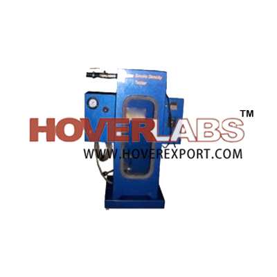


Smoke Density Tester
Model No. PTE003

Smoke Density Chamber is constructed using 14 gage aluminum
box, which is hinged a heat resistant glass glazed door. This box is mounted on
the base which houses the controls. Dependent upon the materials tested, the
metal may require protection from corrosion. The chamber is sealed except for
25 by 30mm (1by 9in.) openings on the four sides of the bottom of the chamber.
A liters/min specified capacity blower is mounted on one side of the chamber.
The inlet duct to the bowler is equipped with a close fitting damper. The
outlet of the bowler will be connected through a duct to the laboratory exhaust
system. The two sides adjacent to the door are fitted with 70mm (2/3in)
diameter smoke tight glazed areas entered 480mm (19/4 in.) above the base. At
these locations and out side the chamber, boxes containing the optical
equipment and additional controls are attached. A removable white plastic plate
is attached to the back of the chamber. There is a clear area centered above
the bottom of the chamber. Through which is seen an illuminated white on red
exit sign. The white back ground permits observations of the flame, smoke, and
burning characteristics of the materials. The viewing of the exit sign helps to
correlate visibility and measured values. The specimen holder is supported on a
square gage. Stainless steel wire cloth above the base and equidistant from all
sides of the chamber. This screen is lying in a stainless steel bezel supported
by a rod through the right side of the chamber. From the same rod similar bezel
is located below and it is support a square of asbestos paper which catches any
particles that may drip from the specimen during the test. By rotating the
specimen holder rod, the burning specimen can be quenched in a shallow pan of
water positioned below the specimen holder.
The specimen is ignited by a propane flame from a burner
operating at a specified pressure. The fuel is mixed with air which has been
propelled through the burner by the venturi effect of the propane as it passes
from small orifice. The burner is designed to provide adequate outside air. the
burner is capable of being positioned quickly under the specimen so that the
exit of the burner falls on a line passing through a point 8mm above the base
at one corner of the chamber extending diagonally across the chamber and
sloping up wards at 45 deg with the base. There is a control panel which
control and indicate the supply of gas. Lux of light measurement system of the
mounted light source also mounted in the instrument. There is a digital timer
mounted in the instrument to indicate the time.
E: info@hoverexport.com w: www.hoverexport.com M: +91 94666 93111