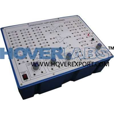


Operational Amplifier Trainer
Model No. HV-EXP2182

Practical experience on this board carries great educative value for Science and Engineering Students. List of experiments Following experiments can be performed : 01. Basic operational amplifier circuit 01. Inverting amplifier 02. Non-inverting amplifier 03. Inverting A.C. amplifier 04. Non-inverting A.C. amplifier 05. High input impedance inverting amplifier 06. High input impedance non-inverting amplifier 02. SOURCE FOLLOWERS 01. Voltage Follower (Unit gain buffer amplifier) 02. A.C. Voltage follower 03. OP- AMPS AS ANALOGUE COMPUTER ELEMENTS 01. Inverting summing amplifier 02. Non-inverting summing amplifier 03. Subtractor 04. Differential amplifier 05. A.C. differential amplifier 06. Adder subtractor 07. Multiplication by aconstant 08. Division by aconstant 09. Integrating amplifier for DC input signals 10. Integrating amplifier for AC input signals 11. Differentiator amplifier 12. Non-inverting differentiator 04. FUNCTION GENERATOR 01. Sine Wave generator using wien bridge network 02. Square Wave generator 03. Pulse generator 04. Square and Triangular wave generator 05. Saw tooth generator 06. Synchronised sawtooth generator with negative going pulse trigger 07. Synchronised sawtooth generator with positive going pulse trigger 05. MULTIVIBRATORS 01. Astable multivibrator 02. Monostable multivibrator 03. Bistable multivibrator 06. FILTERS 01. Low pass active filter 02. High pass active filter 03. Band pass active filter 04. Notch filter 07. VOLTAGE AND CURRENT REGULATOR 01. Basic reference voltage source 02. Basic reference voltage source with buffered output 03. Basic reference voltage source with negative output 04. Negative voltage reference source with buffered output 05. Positive regulator with variable buffered output 06. Negative regulator with variable buffered output 07. Buffered reference source 08. Basic non-inverting voltage controlled current source 08. SIGN CHANGER 01. Sign changer with variable output 02. Switch select sign changer 09. PHASE SHIFT CIRCUIT 01. Constant amplitude lag circuit 02. Constant amplitude lead circuit 10. SIGNAL PROCESSING CIRCUITS 01. Diodes 01. Precision Diode with +O/P 02. Precision Diode with -O/P 02. Rectifier 01. Half wave rectifier 02. Full wave rectifier 03. Filtered full wave rectifier 03. Detectors 01. Peak detector 02. Buffered peak detector 03. Inverting peak detector 04. Zero crossing detector 05. Buffered zero crossing 04. Clippers 01. Positive peak clipper 02. Negative peak clipper 03. Self buffered series clipper 04. Shunt clipper 05. DC restorer 05. Dead Band Response 01. Feed back circuit with dead band response 02. Variable dead band circuit 11. LIMITERS 01. General purpose unipolar limiter 02. Bipolar zener limiter 03. Input current limiter 04. Diode bridge limiter using one zener 05. Adjustable bipolar limiter 12. COMPARATORS 01. Fast precision voltage comparator 02. Single ended comparator with hysteresis & clamped feed back 03. Comparator for signals of opposite polarity 04. Comparator for A.C. coupled signals 13. INSTRUMENTATION AMPLIFIER 01. Basic differential input instrumentation amplifier 02. Instrumentation amplifier with high input impedance 14. OUTPUT DISPLAYS FOR COMPARATOR 01. LED driver 02. Lamp driver 15. METERING CIRCUITS 01. D.C. voltmeter 02. D.C. ammeter 03. Resistance to voltage converter....
E: info@hoverexport.com w: www.hoverexport.com M: +91 94666 93111