Peripheral Study Cards
Model HV-EXP2288
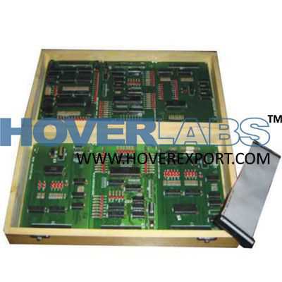
Study Cards can be connected to the 50 Pins KXT Bus of any 8/16 bit Series Microprocessor Trainer Kits. In this Study Card LED's are provided for different signals like Read, Write, Address Lines,Data Lines, Chip Select & Ports depending upon the Peripherals. Study (PPI) STUDY CARD 24 bit I/O using Programmable Peripheral IC All Input/Output ports pins are terminated on 3eight pin terminals & 26 pin FRC Connector All Input/Output ports are indicated by 3mm LEDs Data lines from AD0 to AD7 are indicated by 3mm LEDs Chip Select, A0, A1, Read, Write are indicated by 3mm LEDs Hardware Single Step and Full Clock Execution mode are provided Single stepping can be performed using micro switch provided on board Using this study card all MODE experiment can be performed Interface Kit using 50 pin FRC Connector User's Manual with Sample Programs (PTC) STUDY CARD Three channel Timer/Counter using Programmable Timer Counter IC All Input/Output ports pins are terminated on terminals & 10 pin FRC Connector Clock for Counter-0 is internally provided Data lines from AD0 to AD7 are indicated by 3mm LEDs Chip Select, A0, A1, Read, Write are indicated by 3mm LEDs Hardware Single Step and Full Clock Execution modes are provided Single stepping can be performed using micro switch provided on board Card are supplied in Australian Pine Wood Enclosure Using this study card all MODE experiment can be performed Interface Kit using 50 pin FRC Connector User's Manual with Sample Programs (PPI WITH TIMER) STUDY CARD 22 bit I/O with single channel timer using 8155 Programmable Peripherals IC All Input/Output ports pins are terminated on 3eight pin terminals & 26 pin FRC Connector All Input/Output ports are indicated by 3mm LEDs Data lines from AD0 to AD7 are indicated by 3mm LEDs Chip Select, IO, Memory, Read, Write are indicated by 3mm LEDs Hardware Single Step and Full Clock Execution modes are provided Single stepping can be performed using micro switch provided on board Using this study card all MODE experiment can be performed Interface Kit using 50 pin FRC Connector User's Manual with Sample Programs (USART) STUDY CARD Serial communication using Universal Synchronous/ Asynchronous Receiver Transmitter IC Output are provided on 9pin D-Type connector Data lines from AD0 to AD7 are indicated by 3mm LEDs Chip Select, Read, Write, A0, A1, DTR, DSR, RTS, CTS, TxRDY, RxRDY are indicated by 3mm LEDs Hardware Single Step and Full Clock Execution modes are provided Single stepping can be performed using micro switch provided on board Using this study card all MODE experiment can be performed Interface Kit using 50 pin FRC Connector User's Manual with Sample Programs.