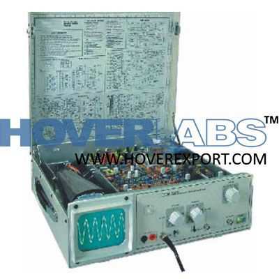
Oscilloscope Demonstrator Trainer

Model HV-EXP2232
Oscilloscope demonstrator trainer is specifically designed for the study of working of an oscilloscope in an open form. The controls are placed actually at the place as they are in the layout schematic. Thus atrainee can easily locate any section, & components in the section and study it thoroughly. The function controls and the adjustment controls are fully accessible to the trainee to verify their effect on the working of the scope. Creation of faults and rectification of faults are important exercise covered in the experiments. An illustrated block and circuit schematic and the adjustment plan right in front of the trainee's eyes helps him tocorrelate each operation during the demonstration. Oscilloscope in open form with all components andcontrols placed on single PCB Amplifier, Time base, Channel section signalavailable on test points Separate sections for PS, EHT, VA, HA, TB &Trigger for easy identification Fault creation & rectification provided Track printing with different colours on differentsections on component board for easy circuit training Legend Printing on PCB for easy identification ofcomponents Can be used as astandard 20 MHz Dual TraceOscilloscope Technical Specifications Operating Modes Channel I, Channel II, Channel I& II Alternate or chopped, Controls provided on PCB. Channel selection signals available at Test points. X-Y operation 1:1 Vertical deflection (Y): (Identical channels) Bandwidth :DC-20 MHz (-3 dB) Risetime :17.5 ns (approx.) Deflection coefficients :12 calibrated steps 5mV /cm -20 V/cm (1-2-5 sequence) Accuracy :±3 % Input Impedance :1MW II 30 pF Input coupling :DC -AC -GND Maximum Input voltage :350 V(DC +Peak AC) Pre-Amp, FinalAmp Outputs at Test Points. Timebase: Time coefficients :18 calibrated steps, 0.5 ìs /cm -0.2 s/cm (1-2-5 sequence) with magnifier x5to 100 ns /cm, with variable controlto 40 ns /cm Accuracy :± 3%(in Cal position) TB generationat Test Points Sweep Output :5V(approx.) Trigger System: Modes :Automatic or Variable Source :CH I, CH II, External Slope :Positive or Negative Coupling :AC, TV Frame Sensitivity :Int 5mm, Ext 1V(approx.) Trigger Bandwidth :30 Mhz Horizontal Deflection (X) Bandwidth :DC -2MHz (-3 dB) X-Ymode :Phase Shift < 5° at 50 KHz Deflection coefficients :12 calibrated steps 5mV /cm -20 V/cm (1-2-5 sequence) Input Impedance :1MW II 30 pF Component Tester : Test Voltage :Max 8.6 V(Open) rms Test Current :Max 8mA (Shorted) rms Test Frequency :50 Hz, Test circuit grounded to chassis....


