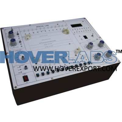
Digital Lab
Model HV-EXP2189
The Digital Lab is intended for elementary as well as advance training of digital electronics. The digital lab covers regular digital circuits bysolder-less interconnections on breadboard and as well as compatible with all optional modules through use of 2mm brass terminals and patchcords. Various clock generators, logic level input/output indicators and DC regulated power supplies etc. are in-built. The unit housed inattractive enclosure is supplied with mains cord, patch cords, Instruction manual andComponent Set. Experimental Coverage: Logic gates operation To verify De-morgan’s theorem with boolean logic equations Binary to Gray code conversion Gray code to Binary conversion Binary to Excess-3 code conversion Binary Adder and Subtractor Binary Multiplier EX-OR gate implementation Application of EX-OR gate Johnson Counter To verify the dual nature of Logic Gates Study of Flip-Flops RS, JK, D&T Multiplexer and Demultiplexer 4Bit Binary up and down counter Study of 8to 3Line Encoder Study of 3to 8Line Decoder Study of Shift Register (SIPO) CMOS-TTL Interfacing Study of Crystal oscillator Study of pulse stretcher circuit Features: Bread Board :Unique solder-less large size, spring loaded breadboard consisting of two Terminal Strips with 1280 tiepoints and 4Distribution Strips with 100 tie points each, totaling to 1680 tie points. (Size :112mm x170mm approx) Regulated DC Power Supply :+5V at 1Amp, -5V at 500 mA, 3to +15V at 500mA, and -3 to -15V at 500 mA. Pulse Generator :1Hz to 1MHz in 6Steps. Variable in between steps -Amplitude :3-15V (CMOS), 5V (TTL) -Duty Cycle :50% TTL /CMOS Output Pulsar Switches :2independent buffered bounce free manual pulser (useful for freezing the action of each stage of thecounter after every clock pulse) Data Switches :12 Nos. independent buffered logic level inputs to select High /Low TTL levels, each with abi-colorLED to indicate high /low status and termination. Logic Indicators :12 Nos. independent buffered logic level indicators for High /Low status indication with bi-color LEDfor digital outputs Seven Segment Display :2Nos. BCD to Seven Segment Decoder /Driver IC with terminals Logic Probe :Logic level indicator for TTL /CMOS CMOS/TTL :Provided Power :230 V± 10%, 50 Hz Components Provided :ICs-4001/1, 4049/1,4069/1, 7400/1, 7402/1, 7404/1, 7406/1, 7408/2, 7410/2, 7411/3, 7420/2,7432/3,7474/2,7476/2,7486/1.Resistors-330E/1,1K/2, 1K8/1,,15K/1, 47K/1.1M/2, Capacitors- 0.01mF/1,0.1mF/1, 0.22 mF/1,Crystal-32.768MHz/1. Accessories :Mains cord, Operating and Experimental manual, Red & Black patch cords (2mm with Pin) 10 each,Red & Black patch cord (Pin to Pin) 10 each. Wire 24/25 SWG. 1Meter each 5 Color Instructionmanual :Strongly supported by detailed operating instructions. Weight :5Kg. (Approx.) Dimension :W412 xH150 xD310....