Bread Board Circuit Lab
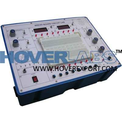
Model HV-EXP2196
The Bread Board Circuit Labis intended for elementary as well as advance training of analog electronics. The trainer cover regular analog circuits by solder less inter connections through use of 2mm brass terminations & patch cords. Various AC & DC regulated power supply in built. The unit is housed in sun mica finished wooden enclosure with provision for safe keeping of mains cord, patch cords and top lid for protection during storage. The Trainer Cover The Following Experiment : 01. Study of basic gates and verification of their truth tables: 02. Study and verifications of the law of Boolean algebra and De-Morgan’s Theorems. 03. Study of important TTL terminologies. Verification of important TTL Circuit parameters. 04. Construction and verification of various types of flip -flops using gates and IC’s : 05. Construction and verification of various types of combinational circuits : 06. Construction and verification of various types of counters : 07. Construction and Verification of 4Bit Universal Shift Register : 08. Many other experiments are possible using the onboard components and Bread board . Feature: Bread boards: Unique solder-less large size, spring loaded breadboard consisting of two Terminal Strips with 1280 tie points and 4Distribution Strips with 100 tie points each, totaling to 1680 tie points. (Size:112mm x170mm approx) IC based DC Reg.: (a). +12 V/500 mA (fixed and with facility to vary from 0to +12 V). Power Supplies: :(b). -12 V/500 mA (fixed and with facility to vary from 0to -12 V). :(c). +5V ± 0.25V /500mA (fixed ). Digital meters: :(a) Dual range DC voltmeter (20 V/200V ). (3.5 Digit) :(b) Dual range DC current meter (200 mA /2A ). Continuity Tester: Audio /Visual indication. Clock Generators: (a). 0.1Hz, b. 1Hz, c. 100Hz, d. 1KHz. Simultaneous independent fixed TTL (5V )outputs. Manual Pulser: One independent buffered bounce less manual pulser (useful for freezing the action of each stage of the counter after every clock pulse ) Logic Level Inputs: Eight independent buffered logic level inputs to select High /Low TTL levels, each with aLED to indicate high /low status and termination. Logic Level: Eight independent buffered logic level indicators for High /Low status indication Indicators of digital outputs. AC Supplies: 9-0-9VAC /500 mA. Speaker:8ohms miniature speaker with terminations. Potentiometers:3Potentiometers (1K, 10K and 100K )with terminations. Power ON:Power ON switch with indicator for mains on indication and fuse for protection. Patch Cords: a. Set of 25 assorted colored single stand hook -up wires. b. Set of 15 assorted colored multi -stand wires with 2mm stackable plug termination at one end & hook-up wire termination at the other end. Components provided:IC-7400/1, 7402/1, 7408/1, 7432/1, 7404/1, 7490/1, 7495/1, 7486/1, 7476/2, 7410/2. Power Requirement:230V +10% single phase AC. Weight :5Kg. (Approx.) Dimension :W412 xH150 xD310.