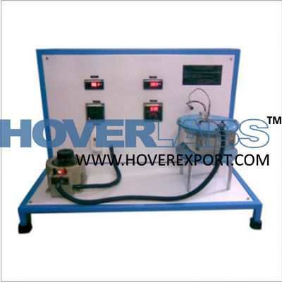
APPARATUS FOR DETERMINING THE CRITICAL POINT

Model HV-EXP2438
APPARATUS FOR DETERMINING THE CRITICAL POINT This very accurate apparatus is used to study the compression and the liquefaction of gas, to determine the critic point, and to detect isothermal lines on diagram p-V ( Clapeyron diagram). The gas under test is the sulfur hexafl uoride (SF6) that reaches its critical temperature at 318,6 K (45,5°) and its critical pressure of 3,76 MPa (37,6 bar), and it enables to create a simple structure. This apparatus includes a transparent measure cell, that it is particularly hermetic and resistant to pressure. An adjustable wheel enables to vary the internal volume of the cell: the variation of the volume is indicated on fi xed and rotating scales, with an accuracy rating of 1/1000 of the maximum volume. Pressure is output by a hydraulic system containing castor oil of good quality for medical purpose. The measuring cell and the hydraulic system are separated by a membrane that moves as the volumes increases. Consequently the pressure gradient between the measuring cell and the chamber of oil, is negligible. A pressure gauge measures oil pressure instead of gas pressure, without any dead volume inside the measuring cell. Thus, during the transition from gaseous to liquid phase, and vice versa, it is possible to observe how the fi rst drop of liquid forms, and how the last gas bubble disappears. The measuring cell is closed in a transparent water chamber. A circulation thermostat enables to keep a constant temperature, that can be easily set, read and checked with a thermometer. Thus it is easy to plot volume, pressure and temperature on p-V or pV-p diagrams, obtaining good results from a qualitative point of view. Pressure and volumetric corrections depending on temperature, lead to accurate results from a quantitative point of view (respect to reference standard values). TRAINING PROGRAM Liquid and gaseous state • Dynamic state during compression and decompression phase • Critical opalescence • Determination of transition point at different temperatures Quantitative measurements • Explanation of critical point and of critical temperature • Detection of isothermal lines in p-V diagram (Clapeyron diagram) • Detection of isothermal lines in pV-p diagram (Amegat diagram) • Pressure waves of saturated steam • Deviations of real gas from ideal gas state TECHNICAL CHARACTERISTICS Critical temperature: 318.5 K (45.5°C) Critical pressure: 3.76 Mpa (37.6 bars) Critical volume: 197.4 cm3/mole Critical density: 0.74 g/mole Temperature range: 10 – 60°C Maximum pressure: 6.0 Mpa (60 bars) Maximum volume: 15.7 cm3 Diameter of pressure gauge: 160 mm Orifi ce for temperature sensor: diameter of 6 mm Connections through thermal instrument/means: 7 mm diameter Connections of valve’s reducer: 1/8’’ diameter Standard gas connection: 3.5 mm diameter Dimensions: 380 x 200 x 400 mm Weight: approximately 7 kg Components This equipment includes: • Apparatus for critical point determination: it is fi lled with hydraulic oil (castor oil) but without gas test (SF6), it has a gas connection mounted on gas bomb MINICAN® and a protection for gas tube connection • 1 oil fi lling device • Angled Allen wrench of 1,3 mm for locking screw of turntable scale • 1 fl exible hose of plastic material, 3 mm inner diameter • 1 1/8”pipe connection tube (11) • 1 oiler • 1 silicon tube 6 mm • 1 gas MINICAN® container • 1 pressure regulator • 1 immersion thermostat • 1 pressure gauge • 2 thermometers.


